CHAAOS 2
CHAAOS 2
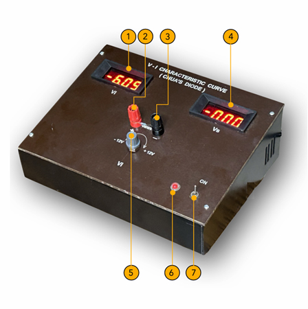
| Reference Number | Description |
|---|---|
| 1 | Output to CRO (x-axis) of the signal x(t) |
| 2 | Output to CRO (y-axis) of the signal y(t) |
| 3 | Coarse variation of resistance R |
| 4 | Fine variation of resistance R |
| 5 | ON/OFF switch |
| 6 | 230V India power plug (50 Hz) |
Key features:
Chua's circuit is straightforward, comprising just a few essential components – resistors, capacitors, an inductor, and a nonlinear element (usually a Chua diode). This simplicity makes it an accessible and straightforward system to study.
Chaotic behavior: Despite its simplicity, the circuit produces a complex, non-repeating waveform – a hallmark of chaos. The "double scroll" attractor visually represents this chaotic output.
Significance: It is a ubiquitous real-world example of a chaotic system, demonstrating chaos theory's principles. Its ease of construction makes it popular in education and research.
Applications and implications:
Research: Chua's circuit is a valuable tool for studying chaotic systems, helping researchers understand the complexities of nonlinear dynamics.
With its simplicity and clear demonstration of chaos, Chua's circuit is a valuable research tool and an inspiring teaching aid. It sparks curiosity and provides a solid introduction to the captivating field of chaos theory. Its potential applications in secure communication, random number generation, and music synthesis further underscore its educational value.
References: 1. Michael Peter Kennedy, “ Robust op-amp realisation of Chua’s circuit”, Frequenz 46, 66-80 (1992). 2. M.Lakshmanan and K.Murali, “Chaos in nonlinear oscillators”, World Scientific, Singapore (1996). Chaotic Dynamics of Chua’s circuit
Objective To study the bifurcations and chaotic dynamics of the Chua’s autonomous circuit.
Apparatus and Materials
- Chua’s chaos circuit kit
- Dual channel oscilloscope (1 No.)
- CRO probes (BNC connectors) (2 Nos).
Background Information
Chua’s circuit is a simple oscillator circuit which exhibits a variety of bifurcations and chaos. It contains three linear energy storage elements (an inductor and two capacitors), a linear resistor, and a single nonlinear resistor, namely the Chua’s diode (N). The operational region of the Chua’s diode will be confirmed to a three segment piecewise-linear part of the V-i characteristic curve. The Chua’s diode (N) circuit is then constructed using an Analog Devices AD712 or µA 741 op-amp, a dual regulated 9V power supply and six linear resistors. Figure 1 shows practical implementation of Chua’s circuit. This is the circuit actually been used in the kit.
The circuit component values are fixed as inductor L = 18 mH, capacitor C1 = 10 nF, C2 = 100 nF and by reducing the variable resistor (R) from 5000 Ω towards zero, Chua’s circuit is readily seen to exhibit a sequence of bifurcations, from dc equilibrium through a Hopf bifurcation and period-doubling sequence to a single spiral-Chua attractor and a double scroll Chua attractor as illustrated in Fig. 2.
In the experimental study, a two-dimensional projection of the attractor is obtained by connecting the voltage across the capacitor C1 (BNC connector terminal 1), voltage across the capacitor C2 (BNC connector terminal 2) to the x-axis and y-axis of the oscilloscope respectively, one can observe the phase-portraits of periodic limit cycles and chaotic attractor by varying the resistor R (knobs 3 and 4). By applying Kirchoff’s laws to the circuit of Fig.1, the following coupled first-order differential equations are obtained:
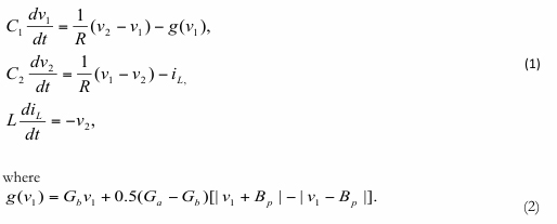
Here g(v1) is the piecewise-linear function, which is the mathematical representation of the characteristic curve of the Chua’s diode. The actual values of Ga, Gb and Bp are fixed as -0.76 ms, -0.41 ms and 1.0 V respectively.
Experimental procedure
- Connect the one end of the provided BNC cables to Channel-1 and Channel-2 of the dual channel oscilloscope. Connect the other ends of the BNC cables to terminals 1 and 2 respectively in the kit.
- Connect the 230V India power plug (50Hz) to the rear end of the kit (Reference No. 6).
- Switch ON the kit (Reference No.5)
- Vary the resistance in the trimpot R (coarse) (Reference No.3) carefully in the kit until you observe a period-1 limit cycle (phase-portrait) in the oscilloscope as shown in Fig.4(a). Take a photo.
- Decrease slowly the trimpot R (coarse) until you observe a period-2 limit cycle in the oscilloscope as shown in Fig.4(b). Take a photo.
- Now slowly vary the trimpot R (fine) (Reference 4) until you observe a period-4 limit cycle in the oscilloscope as shown in Fig.4(c). Take a photo.
- Vary slowly the resistance R (coarse) until you observe a single-band chaotic attractor in the oscilloscope as shown in Fig.4(d). Take a photo.
- Vary slowly the resistance R(Coarse) until you observe a double-band chaotic attractor in the oscilloscope as shown in Fig.4(e). Take a photo.
- Decrease slowly further the resistance R(fine) until you observe another double-band chaotic attractor in the oscilloscope as shown in Fig.4(f).
- Slowly decrease the value of R further, observe period-3 limit cycle, period-5 limit cycle and period-1 boundary.
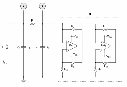
Fig.1. Experimental realization of the Chua’s autonomous circuit. The Chua’s diode (N) is realized with six resistors and two op-amps OA1 and OA2. The op-amps are AD712, µA741, TL082 or equivalent. Here inductor L = 18 mH (TOKO type 10RB, Coilcraft type RFC0810B-186KE, or equivalent), Capacitors C1 = 10nF, C2 = 100nF, R= Trimpot 5 KΩ, Resistors R1 = R2 = 220 Ω, R3 = 2.2 KΩ, R4 = R5 = 22 KΩ, and R6 = 3.3KΩ [1-2]. The supply voltages are fixed as Vcc = +9V and VEE = -9V.
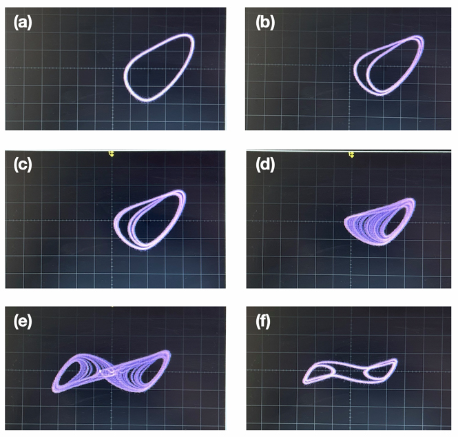
Fig.2. Phase-portraits: (x(t) versus y(t) plot). Here x(t) and y(t) correspond to voltage V1 and voltage V2 across the capacitors C1 and C2 respectively from Fig.1. Terminal 1 output (from kit) to channel-1 and terminal-2 output (from kit) to channel-2 of the oscilloscope. Typical period-doubling bifurcation sequences exhibited by the Chua’s circuit: (a) R=1.88kΩ, period-1 cycle; (b) R=1.85kΩ, period-2 cycle; (c) R=1.84kΩ, period-4 cycle; (d) R=1.79kΩ, single-scroll chaotic attractor; (e) R=1.74kΩ, double-scroll chaotic attractor; (f) R=1.68kΩ, period-3 cycle. Vertical axis 2V/div. and horizontal axis 5V/div.
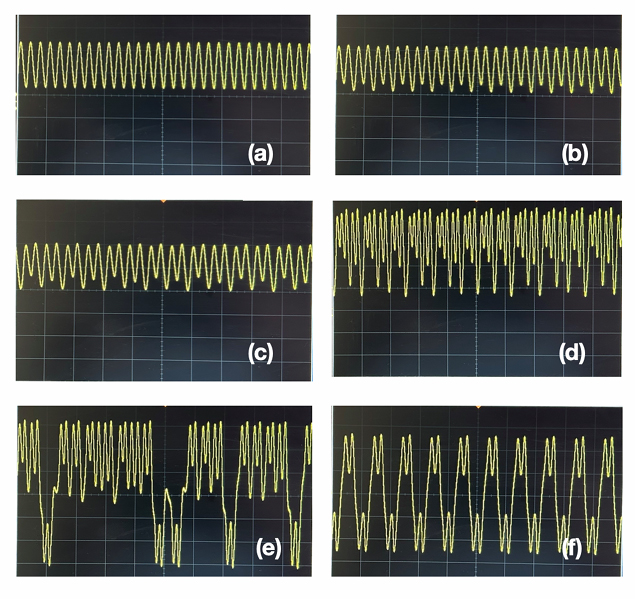
Fig.3. Waveform x(t) corresponds to the voltage across the capacitor C1 from Fig.1. Terminal 1 output (from kit) to channel-1 of the oscilloscope. Typical period-doubling bifurcation sequences exhibited by the Chua’s circuit: (a) R=1.88kΩ, period-1 cycle; (b) R=1.85kΩ, period-2 cycle; (c) R=1.84kΩ, period-4 cycle; (d) R=1.79kΩ, single-scroll chaotic attractor; (e) R=1.74kΩ, double-scroll chaotic attractor; (f) R=1.68kΩ, period-3 cycle. (a)-(c): Vertical axis 10V/div. and horizontal axis 1ms/div. (d)-(f): Vertical axis 5V/div. and horizontal axis 2ms/div.
Precautions
- Result
- Make sure the ground terminals of the kit, and oscilloscopes are properly connected.
- Do not short circuit the power supply.
Our nonlinear electronic circuit kits are designed to offer a hands-on platform for exploring chaotic systems' complex and unpredictable behaviour through electronic circuits.
Key Features:
Variety of Circuits: Experiment with classic and contemporary nonlinear electronic circuits, including Chua's diode characteristics kit, Chua's chaos circuit, and Murali-Lakshmanan-Chua (MLC) chaos circuit.
Real-time Visualization: Observe chaotic attractors and waveforms in real-time with an oscilloscope (not included) to better understand their dynamic nature.
Detailed Manual:This comprehensive guide includes detailed instructions and theoretical explanations, fostering a thorough understanding of chaos theory principles.
Versatile Learning Tool: Ideal for students, educators, researchers, and electronics enthusiasts interested in exploring complex nonlinear systems.
Educational and Research Benefits:
Fundamental Understanding:
Gain insight into core chaos theory concepts, such as sensitivity to initial conditions, strange attractors, and fractal dimensions.
Hands-On Skill Development:
Acquire practical expertise in designing, constructing, and analyzing chaotic circuits.
Critical Thinking Enhancement:
Cultivate problem-solving and analytical skills within nonlinear systems.
Real-World Applications:
Explore the diverse applications of chaos theory in fields such as weather prediction, cryptography, and secure communications.
Target Audience:
Higher Education:
Undergraduate and graduate students in physics, engineering, mathematics, and related disciplines. Educators: Professors and teachers seeking engaging, hands-on experiments to enrich their curriculum. Research Institutions: Laboratories and research centers dedicated to advancing the understanding of nonlinear dynamics and its applications.
Electronics Enthusiasts:
Hobbyists and individuals with a passion for electronics and a curiosity for exploring complex systems.
“The butterfly effect suggests small changes can have significant, unpredictable consequences. This is part of chaos theory, where deterministic nonlinear systems can produce seemingly aperiodic outputs without noisy inputs”. Our premium Chaos Electronic Circuit Kits are not just tools, but gateways to understanding and experiencing the power of chaos. Each kit includes carefully curated circuits and a comprehensive experiment manual, making it an invaluable resource for students and educators alike.
Helpline and Support
+91 44 43302775