CHAAOS 1
CHAAOS 1
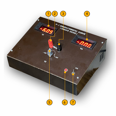
| Reference Number | Description |
|---|---|
| 1 | Volt meter for input voltage(Vi) |
| 2 | Current sensing resistor (Rs) terminal 1 |
| 3 | Current sensing resistor (Rs) terminal 2 |
| 4 | Volt meter for output voltage (Vs) |
| 5 | Input voltage (Vi) knob |
| 6 | Instrument ON/OFF LED indicator |
| 7 | ON/OFF switch |
Characteristics
- Piecewise-Linear: Chua's diode is characterized by a piecewise-linear current-voltage (I-V) relationship. This means its behavior is defined by different linear segments across various voltage ranges.
- Negative Resistance Region: A critical feature is the presence of a negative resistance region in its I-V curve. In this region, an increase in voltage leads to a decrease in current, contrary to typical resistive behavior. This negative resistance is instrumental in generating the oscillations and chaotic behavior observed in Chua's circuit.
Chua's diode is often implemented using operational amplifiers (op-amps) and diodes. The op-amps are configured to create the desired piecewise-linear I-V characteristic, while the diodes help shape the negative resistance region.
Mathematical Representation
The I-V relationship of Chua's diode can be mathematically expressed as:

where, I: Current through the diode, V: Voltage across the diode, Ga: Conductance (slope) of the inner segment(s), Gb: Conductance (slope) of the outer segment(s), Bp: Breakpoint voltage, where the slope changes. The negative resistance region of Chua's diode acts as an energy source, injecting energy into the Chua’s chaotic circuit at specific voltage levels. This energy injection, coupled with the circuit's reactive elements (capacitors and inductor), leads to the sustained oscillations and complex, non repeating patterns characteristic of chaotic systems.
Beyond Chua's Circuit
While primarily associated with Chua's circuit, the concept of a nonlinear resistor with a negative resistance region has implications beyond chaos theory. It finds applications in various electronic circuits and systems where controlled oscillations or nonlinear behavior is desired. For example, it is the only source of nonlinearity in the Murali-Lakshmanan-Chua (MLC) non-autonomous chaotic circuit.
References [1] Chua, L. O., “The genesis of Chua's circuit”, Archiv für Elektronik und Übertragungstechnik, 46(4), 250-257 (1992).
[2] Kennedy, M. P., “Robust op-amp realization of Chua's circuit”, Frequenz, 46(3-4), 66-80 (1992).
[3] M.Lakshmanan and K.Murali, “Chaos in nonlinear oscillators”, World Scientific, Singapore (1996).
Experimental verification of V-I characteristic of the Chua’s diode
Objective
To verify experimentally the V-I characteristic of the Chua’s diode
Apparatus and Materials
- V-I characteristic curve: Chua’s diode kit
- 22 Ω or 33 Ω resistor
Background Information
Chua's diode is often implemented using operational amplifiers (op-amps) and diodes. The op-amps are configured to create the desired piecewise-linear I-V characteristic, while the diodes help shape the negative resistance region. The typical characteristics are
- Piecewise-Linear: Chua's diode is characterized by a piecewise-linear current-voltage (V-I) relationship. This means its behavior is defined by different linear segments across various voltage ranges.
- Negative Resistance Region: A critical feature is the presence of a negative resistance region in its I-V curve. In this region, an increase in voltage leads to a decrease in current, contrary to typical resistive behavior. This negative resistance is instrumental in generating the oscillations and chaotic behavior observed in Chua's circuit. The I-V relationship of Chua's diode can be mathematically expressed as:
- Connect the 230V India power plug (50Hz) from the rear end of the kit.
- Insert the 22Ω resistor between the RED and BLACK terminals (Reference Nos.2 and 3)
- Switch ON the kit (Reference No.7)
- Observe the RED LED is ON (Reference No.6)
- Vary the input voltage (Vi) knob (Reference No.5) to -12V side until you notice 0V in the Voltmeter (Vs)(Reference No.4)
- Note the voltage value (Vi) in Voltmeter (Reference No.3).
- Vary the input voltage (Vi) knob (Reference No.5) from -12V to +12V (clockwise) slowly.
- Note the Voltmeter (Vi) reading (Reference No.1) and Voltmeter (Vs) reading (Reference No.4) and tabulate. Note that for negative (Vi), you get positive (Vs) values.
- Upon varying the input voltage (Vi) knob in clockwise direction, note the reading for which (Vi) = (Vs) = 0V.
- Vary the input voltage (Vi) knob (Reference No.5) further (clockwise) slowly and notice that for positive (Vi), you get negative (Vs) values.
- Note the Voltmeter (Vi) reading (Reference No.1) and Voltmeter (Vs) reading (Reference No.4) and tabulate.
- Vary the input voltage (Vi) knob (Reference No.5) to +12V side until you notice 0V in the Voltmeter (Vs)(Reference No.4).
- Stop taking readings.
- m1 = Vs/Vi = (-1V)/0.585V = -1.71, m2 = Vs/Vi = 0.93V/(-1.0V) = -0.93.
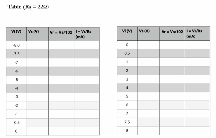
- The gain factor of 102 is used to measure the voltage drop Vs by the voltmeter. Hence, the rescaled voltage is Vr = Vs/102. Then the current is given as I = (Vs/102*Rs) = (Vr/Rs) mA. Here the resistor Rs = 22Ω.
- Now one can plot another graph between the input voltage Vi(V) in x-axis and current I(mA) in the y-axis. Then the calculated slopes of the piecewise-linear resistor are now (I/Vi) Ga = -0.762mS (mA/V) and Gb = -0.414mS (mA/V). The measured breakpoints are Bp = 1V. Refer Fig.4.
- Note that, in SI units, the voltages are measured in Volts (V); currents in Amperes (A); resistance in Ohms (Ω); the reciprocal of resistance, called conductance, is measured in Siemens (S).
- Make sure the ground terminal of the kit, is properly connected.
- Do not short circuit the power supply.
- Do not operate the kit without current provided resistor Rs.
- Plot the full characteristic curve between Vi versus I from the measured values (Refer Table) and calculate the slopes and the breakpoints.
- Use other current sensing resistor values, for example Rs =33Ω, 47Ω,100Ω and measure the slopes and breakpoints from the corresponding characteristic curves.
- Use VIN as a triangular waveform with zero dc offset, amplitude 8V peak-to-peak, and frequency 25Hz in Fig.1. Plot the characteristic curve in a dual-trace oscilloscope with horizontal axis, VIN and vertical axis Vs. Put the oscilloscope in X-Y mode with horizontal axis (2V/div) and vertical axis (100mV/div).

where, I: Current through the diode, V: Voltage across the diode, Ga: Conductance (slope) of the inner segment(s), Gb: Conductance (slope) of the outer segment(s), Bp: Breakpoint voltage, where the slope changes. The negative resistance region of Chua's diode acts as an energy source, injecting energy into the Chua’s chaotic circuit at specific voltage levels. This energy injection, coupled with the circuit's reactive elements (capacitors and inductor), leads to the sustained oscillations and complex, non repeating patterns characteristic of chaotic systems.
Experimental procedure
Figures
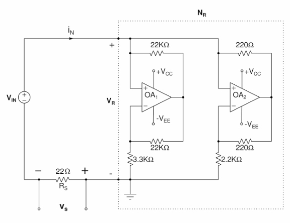
Fig.1. The V-I characteristic of Chua’s diode (NR) can be measured by applying a dc-voltage VIN (from -12V to +12V) to the series combination of Chua’s diode (NR) and a resistor Rs 22Ω. The resistor Rs, known as a current-sensing resistor, is used to measure the current iN which flows into the Chua’s diode NR when a voltage VR is applied across its terminals. The voltage drop (Vs) across the resistor Rs is measured and tabulated. Note that in the negative resistance region(inner slopes), when the input VN is positive, the output Vs is negative and vice-versa. The two op-amps are AD712, µA741, TL082 or equivalent. The supply voltages are fixed as Vcc = +9V and -VEE = -9V [2].
Model Graph
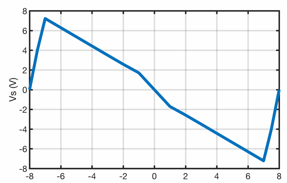
Fig.2. The measured five segment Vi-Vs characteristic of Chua’s diode (NR) for Rs = 22Ω from Fig.1.
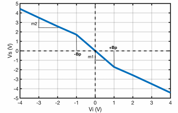
Fig.3. The measured three segment Vi-Vs characteristic of Chua’s diode (NR) for Rs = 22Ω from Fig.1. Here m1 and m2 are slopes. The breakpoints are -Bp = -1V and +Bp = +1V. The measured slopes are m1 = (-1V)/0.585V = -1.71 and m2 = 0.93V/(-1.0V) = -0.93.
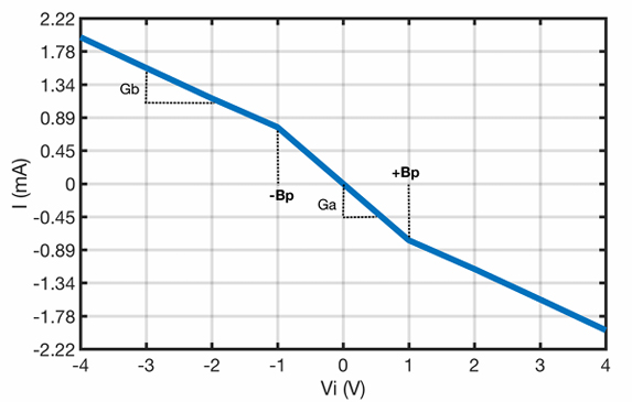
Fig.4. The measured three segment Vi-I characteristic of Chua’s diode (NR) for Rs = 22Ω from Fig.1. Here Ga and Gb are the slopes. The breakpoints are -Bp = -1V and +Bp = +1V. The measured slopes are Ga = -0.762mS and Gb = -0.414mS.
The measured slopes from Fig.3 are:
Precautions
Result
The V-I characteristic curve of the Chua’s diode is measured using the kit. The slopes and the breakpoints are noted down.
Exercises
Helpline and Support
+91 44 43302775